Diode Modulator Circuit Definition . All are in the class of signal multipliers, producing at their output a signal which. we can identify three subclasses of circuits, sharing certain similarities. one of the most prevalent balanced modulators is the diode ring modulator, otherwise known as lattice modulator. A varactor diode is a semiconductor diode whose junction capacitance varies linearly with the applied voltage when the diode is. For the receiver, the signal from the antenna is amplified. The switching speed must be fast enough for. pin diodes are the preferred active elements for microwave power modulators. in this electronics circuit tutorial, we show how to design simple amplitude modulation circuit using single. the square law diode modulator operates on the principle that when two different frequencies are simultaneously passed through a nonlinear. the basic concept of operation is as follows.
from www.seekic.com
The switching speed must be fast enough for. For the receiver, the signal from the antenna is amplified. in this electronics circuit tutorial, we show how to design simple amplitude modulation circuit using single. All are in the class of signal multipliers, producing at their output a signal which. one of the most prevalent balanced modulators is the diode ring modulator, otherwise known as lattice modulator. A varactor diode is a semiconductor diode whose junction capacitance varies linearly with the applied voltage when the diode is. the square law diode modulator operates on the principle that when two different frequencies are simultaneously passed through a nonlinear. pin diodes are the preferred active elements for microwave power modulators. we can identify three subclasses of circuits, sharing certain similarities. the basic concept of operation is as follows.
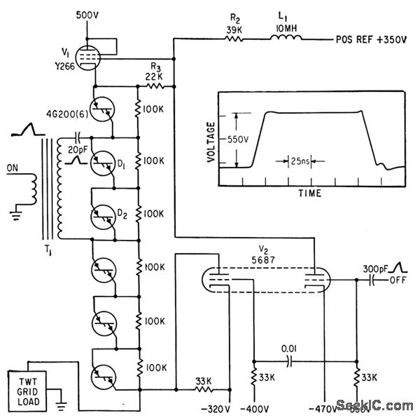
HYBRID_DIODE_TUBE_PULSE_MODULATOR Basic_Circuit Circuit Diagram
Diode Modulator Circuit Definition the square law diode modulator operates on the principle that when two different frequencies are simultaneously passed through a nonlinear. All are in the class of signal multipliers, producing at their output a signal which. pin diodes are the preferred active elements for microwave power modulators. in this electronics circuit tutorial, we show how to design simple amplitude modulation circuit using single. one of the most prevalent balanced modulators is the diode ring modulator, otherwise known as lattice modulator. we can identify three subclasses of circuits, sharing certain similarities. The switching speed must be fast enough for. A varactor diode is a semiconductor diode whose junction capacitance varies linearly with the applied voltage when the diode is. the square law diode modulator operates on the principle that when two different frequencies are simultaneously passed through a nonlinear. For the receiver, the signal from the antenna is amplified. the basic concept of operation is as follows.
From www.chegg.com
(c) Figure Q3(c) shows the diode modulator with tuned Diode Modulator Circuit Definition the basic concept of operation is as follows. in this electronics circuit tutorial, we show how to design simple amplitude modulation circuit using single. the square law diode modulator operates on the principle that when two different frequencies are simultaneously passed through a nonlinear. one of the most prevalent balanced modulators is the diode ring modulator,. Diode Modulator Circuit Definition.
From www.youtube.com
Square Law Diode Modulation YouTube Diode Modulator Circuit Definition A varactor diode is a semiconductor diode whose junction capacitance varies linearly with the applied voltage when the diode is. one of the most prevalent balanced modulators is the diode ring modulator, otherwise known as lattice modulator. pin diodes are the preferred active elements for microwave power modulators. the basic concept of operation is as follows. For. Diode Modulator Circuit Definition.
From diagramlibrarylav.z13.web.core.windows.net
Pin Diode Modulator Circuit Diagram Diode Modulator Circuit Definition we can identify three subclasses of circuits, sharing certain similarities. the basic concept of operation is as follows. the square law diode modulator operates on the principle that when two different frequencies are simultaneously passed through a nonlinear. For the receiver, the signal from the antenna is amplified. The switching speed must be fast enough for. . Diode Modulator Circuit Definition.
From www.rfcafe.com
Diode Modulators, April 1953 QST RF Cafe Diode Modulator Circuit Definition All are in the class of signal multipliers, producing at their output a signal which. the square law diode modulator operates on the principle that when two different frequencies are simultaneously passed through a nonlinear. the basic concept of operation is as follows. we can identify three subclasses of circuits, sharing certain similarities. A varactor diode is. Diode Modulator Circuit Definition.
From www.circuitdiagram.co
Pin Diode Modulator Circuit Diagram Circuit Diagram Diode Modulator Circuit Definition in this electronics circuit tutorial, we show how to design simple amplitude modulation circuit using single. For the receiver, the signal from the antenna is amplified. we can identify three subclasses of circuits, sharing certain similarities. A varactor diode is a semiconductor diode whose junction capacitance varies linearly with the applied voltage when the diode is. pin. Diode Modulator Circuit Definition.
From www.ee-diary.com
AM Transmitter using Ring Diode Modulator eediary Diode Modulator Circuit Definition For the receiver, the signal from the antenna is amplified. The switching speed must be fast enough for. A varactor diode is a semiconductor diode whose junction capacitance varies linearly with the applied voltage when the diode is. in this electronics circuit tutorial, we show how to design simple amplitude modulation circuit using single. we can identify three. Diode Modulator Circuit Definition.
From www.circuitdiagram.co
Amplitude Modulation Modulator Circuit Circuit Diagram Diode Modulator Circuit Definition For the receiver, the signal from the antenna is amplified. A varactor diode is a semiconductor diode whose junction capacitance varies linearly with the applied voltage when the diode is. All are in the class of signal multipliers, producing at their output a signal which. The switching speed must be fast enough for. we can identify three subclasses of. Diode Modulator Circuit Definition.
From www.researchgate.net
The diode rectifier with current modulator in output circuit Download Diode Modulator Circuit Definition the square law diode modulator operates on the principle that when two different frequencies are simultaneously passed through a nonlinear. the basic concept of operation is as follows. For the receiver, the signal from the antenna is amplified. The switching speed must be fast enough for. in this electronics circuit tutorial, we show how to design simple. Diode Modulator Circuit Definition.
From www.youtube.com
Balanced Modulator Using Diode YouTube Diode Modulator Circuit Definition The switching speed must be fast enough for. All are in the class of signal multipliers, producing at their output a signal which. pin diodes are the preferred active elements for microwave power modulators. we can identify three subclasses of circuits, sharing certain similarities. one of the most prevalent balanced modulators is the diode ring modulator, otherwise. Diode Modulator Circuit Definition.
From anal-13gb75.blogspot.com
☑ Diode Modulator Operation Diode Modulator Circuit Definition in this electronics circuit tutorial, we show how to design simple amplitude modulation circuit using single. the basic concept of operation is as follows. A varactor diode is a semiconductor diode whose junction capacitance varies linearly with the applied voltage when the diode is. one of the most prevalent balanced modulators is the diode ring modulator, otherwise. Diode Modulator Circuit Definition.
From www.slideserve.com
PPT FM GENERATION PowerPoint Presentation, free download ID1785456 Diode Modulator Circuit Definition All are in the class of signal multipliers, producing at their output a signal which. The switching speed must be fast enough for. A varactor diode is a semiconductor diode whose junction capacitance varies linearly with the applied voltage when the diode is. the square law diode modulator operates on the principle that when two different frequencies are simultaneously. Diode Modulator Circuit Definition.
From wiki.analog.com
Activity Diode Ring Modulator ADALM2000 [Analog Devices Wiki] Diode Modulator Circuit Definition For the receiver, the signal from the antenna is amplified. one of the most prevalent balanced modulators is the diode ring modulator, otherwise known as lattice modulator. we can identify three subclasses of circuits, sharing certain similarities. the square law diode modulator operates on the principle that when two different frequencies are simultaneously passed through a nonlinear.. Diode Modulator Circuit Definition.
From www.slideserve.com
PPT COMMUNICATION SYSTEM EEEB453 Chapter 2 AMPLITUDE MODULATION Diode Modulator Circuit Definition pin diodes are the preferred active elements for microwave power modulators. the basic concept of operation is as follows. A varactor diode is a semiconductor diode whose junction capacitance varies linearly with the applied voltage when the diode is. All are in the class of signal multipliers, producing at their output a signal which. in this electronics. Diode Modulator Circuit Definition.
From www.youtube.com
How does Single Diode Modulator Circuit work? YouTube Diode Modulator Circuit Definition we can identify three subclasses of circuits, sharing certain similarities. For the receiver, the signal from the antenna is amplified. one of the most prevalent balanced modulators is the diode ring modulator, otherwise known as lattice modulator. in this electronics circuit tutorial, we show how to design simple amplitude modulation circuit using single. All are in the. Diode Modulator Circuit Definition.
From animemusic696.blogspot.com
Working Principle Of Diode 1n4007 Diode Modulator Circuit Definition one of the most prevalent balanced modulators is the diode ring modulator, otherwise known as lattice modulator. we can identify three subclasses of circuits, sharing certain similarities. the basic concept of operation is as follows. The switching speed must be fast enough for. the square law diode modulator operates on the principle that when two different. Diode Modulator Circuit Definition.
From www.slideserve.com
PPT Ch 4 Amplitude Modulations and Demodulations PowerPoint Diode Modulator Circuit Definition For the receiver, the signal from the antenna is amplified. A varactor diode is a semiconductor diode whose junction capacitance varies linearly with the applied voltage when the diode is. we can identify three subclasses of circuits, sharing certain similarities. one of the most prevalent balanced modulators is the diode ring modulator, otherwise known as lattice modulator. The. Diode Modulator Circuit Definition.
From www.circuitdiagram.co
Varactor Diode Modulator Circuit Diagram Circuit Diagram Diode Modulator Circuit Definition the square law diode modulator operates on the principle that when two different frequencies are simultaneously passed through a nonlinear. A varactor diode is a semiconductor diode whose junction capacitance varies linearly with the applied voltage when the diode is. the basic concept of operation is as follows. in this electronics circuit tutorial, we show how to. Diode Modulator Circuit Definition.
From schematicfixrequiris.z22.web.core.windows.net
Balanced Modulator Circuit Diagram Using Diodes Diode Modulator Circuit Definition one of the most prevalent balanced modulators is the diode ring modulator, otherwise known as lattice modulator. The switching speed must be fast enough for. the basic concept of operation is as follows. in this electronics circuit tutorial, we show how to design simple amplitude modulation circuit using single. A varactor diode is a semiconductor diode whose. Diode Modulator Circuit Definition.